| SYSCAD - CAD for metal construction |
|
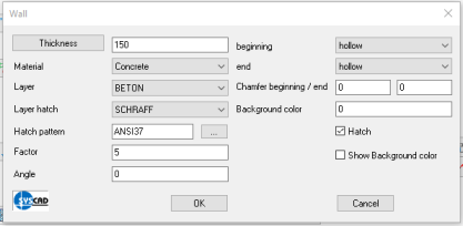
Object draw (Concrete, Wall, Plaster, Sill) |
Attachment details > Object draw |
Drawing of any contour with arbitrary thickness and material. The objects are adjustable via double-click or via moving the grips.
The properties like layers of contour and hatching, type of hatching and distance are defined in the dialog box SYSCAD-Variable / Attachment-Details for 4 further types. Use the command "draw tolerance lines"
The background colour can be set under SYSCAD variable / Connection details / Hatching / Hatching 1-8. With a new command
|