Toolbar: SYSCAD Attachment details -> 
|
|
Ribbon: SYSCAD Attachment details -> Concrete ->
|
|
|
|
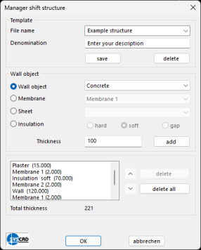
The new Compositions Manager dialogue box enables the combined creation of SYSCAD elements such as wall, concrete, plaster, insulation, membrane or sheet metal.
Create template file:

|
It is possible to create templates in the "Template" area of the layer construction manager dialogue in order to be able to reconstruct drawn layers later.
•Click "save" to save the template.
• An existing template can be deleted using the "delete" button.
•To store a template with your desired shift structure, these must be defined as explained below.
•However, a template file is optional and it is also possible to draw without creating a template file.
|
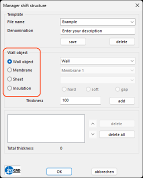
Adding parts to the composition:
To add parts to the composition, whether with or without a template file, the first step is to make a selection between object tension, foil, sheet metal or insulation in order to then display the selection options for the respective SYSCAD objects. The second selection, which template for a SYSCAD object is to be added as a part of the composition, is then made.
|
•In the example, the object train is selected as the first part of the composition.
•Select e.g. concrete, wall, plaster, window sill or your own contour.
•Specify thickness (the thickness is automatically adopted as specified in the template, but can also be changed manually).
•By clicking on the "add" button next to the thickness, the object is entered in the list in which you can see the elements of the layer structure manager.
•To add a sheet to the layer, you must have defined a sheet template. |

|
•Any number of parts can be added to the composition (within the normal CAD possibilities).
•When a part is added to the composition, the total thickness of the existing parts is automatically adjusted.
|
|
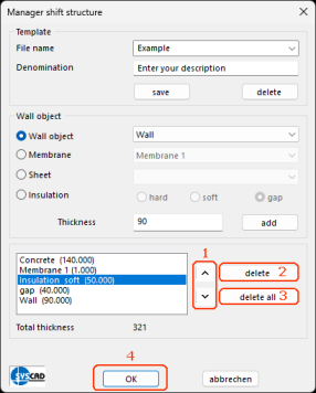
•1. As soon as the list has been filled with the desired parts, the order can be subsequently changed using the arrows to the right of the list field.
•2. The "delete" button deletes the currently selected element from the list.
•3. The "delete all" button removes all existing elements from the list.
•4. When you have finished adding the parts, the dialogue must be closed with "OK" to draw the composition. |
Drawing the compositions in your CAD:
To draw the composition, the user is asked for the starting point, at least one other point and the offset direction.
The offset direction only needs to be entered once and is automatically adopted for all other points.
As soon as the point entry is complete, the layers are drawn automatically.
Double-click function:
Group on  : :

|
•With group mode switched on, the existing composition can be edited with a double-click.
•Double-clicking on an object opens the Manager compositions dialogue and parts can be added or removed as usual.
•The points and the offset direction are retained.
•To change the thickness of the parts, they must be deleted and recreated. You can use the arrows to place them correctly in your composition again.
•When you confirm with the "OK" button, the composition is updated without asking for points and direction again; these are taken from the previous entry.
|
Group off :
|
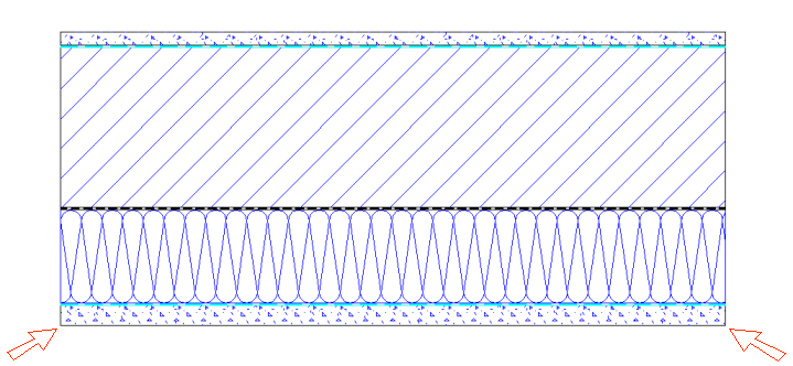
•If group mode is switched off, the manager compositions dialogue only opens when you click on the "outermost" part. See red arrows in the image.
•Double-click on all other objects to open the respective object dialogue (e.g. slide dialogue)
•The thicknesses of the objects should not be changed here.
•You can edit queries for individual objects or the display of objects in this way. |
|