| SYSCAD - CAD for metal construction |
|
Indication of altitude - Block |
Indication of altitude > Example (Block) |
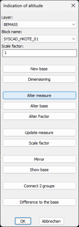
Step 2. Call up the Indication of altitude (block) programme. (SYSCAD programs toolbox -> This opens the dialogue Altitude quotients:
Step 3. We select You will see the following in the command line: Create height node base Define base factor Select block or view, return for input To define the base factor, you can select either a block or a view to apply its factor. Press <Return> to open a dialogue for entering the base factor:
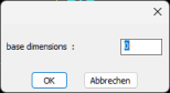
Once you have set your desired factor, the following appears in the command line: Block name <SYSCAD_HKOTE_01> Calculation factor <1.0> Scaling factor <1.0> <SYSCAD_HKOTE_01>: Select the point to be dimensioned Step 4. Select your desired base point in the drawing. Then read in the command line: End point of the reference line You will see a virtual line from the base point - drag the mouse in the desired direction. The end point can be confirmed by clicking the mouse or you can enter a value using the keyboard. Step 5. Set base dimension. The following dialogue appears next:
Your base has been placed.
You should see the following image:
In the command line read: Insertion point height node <SYSCAD_HKOTE_01>: Select the point to be dimensioned Select the 1st point to be dimensioned from the drawing Once you have selected your desired point with the left mouse button, the following appears in the command line: End point of the reference line or <RETURN> for automatic alignment to the base You can therefore create your own guidance line again, or use <Return> or right-click to align your guidance line with the line defined for the base. line defined for the base. Step 6. You place all other desired height vertices in the drawing. Right-click to end the current command.
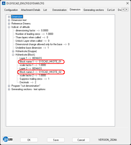
Tip (Indication of Altitude Block): You can change the display of the height note by changing the corresponding block. Thiscan be set in SYSCAD variables / Dimension / Indication of Altitude / Indication of Altitude (block). The block SYSCAD_HKKOTE_01 is located in the SYSCAD directory under TEMPLATES. Change the block and save it under a different name. The name must begin with "SYSCAD_HKOTE_" (the maximum character length is 24). Enter this name in the SYSCAD variable / Dimension / Indication of Altitude / Indication of Altitude (block). From now on, your block will be used when dimensioning with height marks.
|

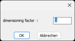

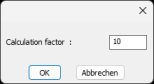 You can enter a factor here. (For example, to work in metres)
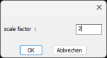 Here you can scale the size of the blocks.
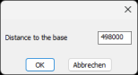 This makes it possible to specify a second measure (difference to the base).