| SYSCAD - CAD for metal construction |
|
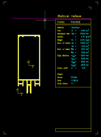
Moment of inertia |
Additional functions > Moment of inertia |
•Run the calculation always in a new drawing. •Drawn elements must be polylines. •If you have seperated contours, SYSCAD asks for the coefficient of interaction (e.g. 0,70). Command: Outer contour: Select objects: Select the outer contours Select objects , which should be subtracted: Select objects: Select the inner contours SYSCAD can hatch the contour of the polylines. It is helpful to control the correct detection of the contours. In case the detection went wrong we recommend the manual selection of the inner and outer contours.
Enter the insertion point of the form and fill in the attributes for the form. In the SYSCAD-Variable / List / form sheet, you can assign different values to 2 variants of the moment of inertia calculation (form Static calculation 1 and 2). You can change the form to suit your requirements.
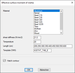
Effective surface moment of inertia for insulated profiles
|